 |
The detector is an intensified photodiode array and is described in
detail by Long et al. (1985). The image intensifier portion of the
detector consists of two 25 mm 80:1, 10 ![]() m pore microchannel plates
(MCP's) and an aluminum-overcoated P 20 phosphor deposited on a 6
m pore microchannel plates
(MCP's) and an aluminum-overcoated P 20 phosphor deposited on a 6 ![]() m pore fiber optic, all mounted into a modified Varian Conflat
flange. The photocathode material is cesium iodide (CsI) deposited,
in a thin layer, directly to the front surface of the top MCP.
Mounted against the back of the intensifier fiber optic is
a 1024 channel Reticon photodiode array. The individual photodiodes
are
m pore fiber optic, all mounted into a modified Varian Conflat
flange. The photocathode material is cesium iodide (CsI) deposited,
in a thin layer, directly to the front surface of the top MCP.
Mounted against the back of the intensifier fiber optic is
a 1024 channel Reticon photodiode array. The individual photodiodes
are ![]() .Individual photon events produce a detectable
signal in about 12 photodiodes. The array is scanned and digitized in
1 msec by the Reticon control electronics, which is mounted close to
the detector on one of the spider arms. The Spectrometer Processor
(SP) then centroids these events to an accuracy of 1/2 diode and
provides a 2048 pixel histogram of the location of each photon on the
detector. This gives a wavelength accuracy of
.Individual photon events produce a detectable
signal in about 12 photodiodes. The array is scanned and digitized in
1 msec by the Reticon control electronics, which is mounted close to
the detector on one of the spider arms. The Spectrometer Processor
(SP) then centroids these events to an accuracy of 1/2 diode and
provides a 2048 pixel histogram of the location of each photon on the
detector. This gives a wavelength accuracy of ![]() 0.5 Å.
In high time-resolution mode the SP also outputs a list of events with their
locations and a time tag accurate to
0.5 Å.
In high time-resolution mode the SP also outputs a list of events with their
locations and a time tag accurate to ![]() msec.
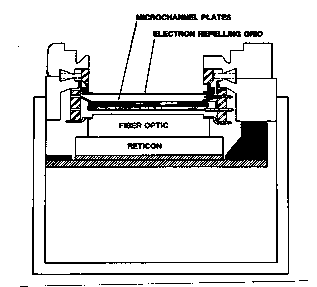
Characteristics of the detector system are listed in Table 1-1 and a
schematic is shown in Figure 2-5.
msec.
Characteristics of the detector system are listed in Table 1-1 and a
schematic is shown in Figure 2-5.