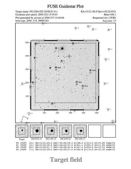
Figure 8‑1: This typical FUSE guide star plot shows the usable guide stars and aperture positions. The pixel coordinate scale is for FES-A. The orientation of North and East is shown in the lower left corner.
The attitude control system (ACS) for FUSE used a quaternion representation for telescope pointing. Although most astronomers are not familiar with quaternions, their advantages for spacecraft control are numerous. Once a target position is parameterized this way, rotational transformations are vastly simplified, particularly because trigonometric functions are not needed. The FUSE archival user does not need to know the details of this system, but will encounter quaternions yielding attitude information from the satellite in the housekeeping file for each exposure (FUSE Data Handbook, Sec. 5.2). This section explains how they can be used to determine telescope pointing during an exposure.
For each fixed target, an observer provided the J2000 right ascension (α) and declination (δ) of the object and selected a science aperture at which to place it (LWRS, MDRS, HIRS, or RFPT). A particular position angle on the sky for the apertures could be requested as well. For moving targets, Mission Planners would use Percy (reference) to generate a table of FUSE-centered (α, δ) vs. time. See Sections 2.4 and 2.7.2, and Figure 2‑10 for a discussion of the FUSE field of view and aperture orientation definitions.
When scheduling an observation, the Mission Planning system calculated the nominal spacecraft roll angle to keep the –X axis of FUSE facing the Sun, with a 2.5° offset to place the radiator of the guiding FES slightly in the shade. For the two-wheel and one-wheel phases of the mission, the roll angle would often be offset further to provide better attitude control with the magnetic torquer bars or to minimize wheel momentum accumulation. For moving targets, the roll angle was determined at the beginning of the exposure and remained fixed along the path.
The planned pointing information is available in the primary header of the FITS files as RA_TARG, DEC_TARG and APER_PA, where the aperture position angle (APER_PA) and spacecraft roll angle are related by
APER_PA = 270° – Roll.
A useful way of visualizing the resultant orientation on the sky is to look at the guide star plot in the MAST archive for the observation. A sample plot is shown below in Figure 8‑1. For this observation, the roll angle was 157.86 degrees and the position angle was 112.14 degrees. The +XIPCS axis points down in these plots.
Figure 8‑1: This typical FUSE guide star plot shows the usable guide stars and aperture positions. The pixel coordinate scale is for FES-A. The orientation of North and East is shown in the lower left corner.
The target coordinates, roll angle, and aperture location were transformed in the SCC into a reference quaternion and aperture offset for uplink to the FUSE IDS. The quaternion product of these values define the location on the sky where the telescope reference point (RFPT, Figure 2‑10) is placed so that the target would be centered in the aperture selected for the exposure. In the housekeeping file, this location is defined by the commanded quaternion values (AQECI2BDYCMD_[1,2,3], FUSE Data Handbook, App. D). These change with time when the spacecraft was slewing, e.g., positioning the target after an acquisition to the aperture or following a moving object, but otherwise remain constant during the exposure of a fixed target. The commanded quaternion is the position the attitude control system was trying to maintain at any time. In addition to the desired pointing, the housekeeping file contains two estimates of the actual pointing. One is the fine pointing data of measured quaternions calculated by the IDS from the guide stars (I_FPD_Q_ECI2BDY_[1,2,3]). The other is the ACS estimate using not only the guide stars, but also vehicle modeling and data from the gyroscopes, magnetometers, and coarse sun sensors (AATTECI2BDY_[1,2,3]). The ACS quaternions are not as accurate without guide star data, such as when tracking was lost. The commanded and measured quaternions were used by CalFUSE to create the jitter file for each exposure, yielding the difference between commanded and actual positions in the X and Y directions usually for every 1or 2 seconds of time, depending on the guiding mode.
The following transformations can be used to convert from quaternions to (α, δ, Roll) of the reference point (RFPT). First note, to conserve space, the housekeeping files only contain three of the four components of the quaternions. In the FUSE convention, the fourth component is the pure rotational one and was forced to be positive by the ACS. Thus, since the quaternion is normalized to one, it can be calculated from the other three components:
q4 = √(1 -q12-q22-q32)
The IDS did not explicitly impose positivity of the fourth component, but because the reference quaternion was generated that way, the full FPD quaternion can be recovered as above for the ACS, except when the fourth component is nearly zero. In that case, if the signs of the other three components are opposite to that of the commanded quaternion, the fourth component needs to be made negative.
The conversion to celestial coordinates of the RFPT is
αJ2000 = atan (q2q3-q1q4, q1q3+q2q4)
δJ2000 = asin (-q12 –q22+q32+q42)
Roll = atan (q2q3+q1q4, -q1q3+q2q4)
where we use a two-argument convention for atan such that atan(y,x) is the arc-tangent of y/x.
The conversion of FES pixel coordinates to celestial coordinates is a multi-step process. The previous section described how to compute the location of the Reference Point (RFPT) on the sky and how to determine the orientation of the IPCS axes relative to North and East. This section provides a prescription for converting raw pixel coordinates to IPCS coordinates.
The first step is to remove the optical distortions in the FES cameras and to flip the FES CCD coordinate axess to match the IPCS coordinate axes. These corrections are applied via third-order polynomials:
xc = a00 + a10x + a01y + a20x2 + a11xy + a02y2 + a30x3 + a21x2y + a12xy2 + a03y3 + fpa_shift_scale * (fpa_xpos – fpa_xrefpos)
yc = b00 + b10x + b01y + b20x2 + b11xy +b02y2 + b30x3 + b21x2y + b12xy2 + b03y3 .
Note that the formula for xc includes a term to correct for the FPA position: the projected positions of the stars shift relative to the telescope boresight by an amount that depends on the FPA position. The FPA x position can be obtained from the FPALXPOS keyword in the FITS headers of FUSE data files; use one of the LiF1 files to obtain the LiF1 FPA position for FES-A images, and a LiF2 file to obtain the LiF2 FPA position for FES-B images. The value of fpa_shift_scale is -0.0127 pix/micron, and fpa_xrefpos is 117 microns for LiF1 and 175 microns for LiF2.
For the sake of completeness, polynomials for converting in the other direction are:
x = c00 + c10xc' + c01yc + c20xc'2 + c11xc'yc + c02yc2 + c30xc'3 + c21xc'2yc + c12xc'ycc2 + c03yc3
y = d00 + d10xc' + d01yc + d20xc'2 + d11xc'yc + d02yc2 + d30xc'3 + d21xc'2yc + d12xc'yc2 + d03yc3
where:
xc' = xc - fpa_shift_scale * (fpa_xpos - fpa_xrefpos).
The polynomial coefficients for FES-A and FES-B are given in Table 8.2‑1 and Table 8.2‑2, respectively.
The second step is to shift the origin from the corner of the FES to the Reference Point, and to convert from pixels to arcseconds:
XIPCS = (xc – xcRFPT) * 2.5505 arcsec/pixel,
YIPCS = (yc – ycRFPT) * 2.5505 arcsec/pixel.
The position of the Reference Point in corrected pixel coordinates is given in Table 8.2‑3. Differences in the mean pixel scale between FES-A and FES-B are absorbed into the distortion coefficients. Note that the RFPT positions in Table 2.7‑3 are given in raw FES coordinates, not corrected coordinates.
| X Correction coefficients |
Y Correction coefficients |
X Distortion coefficients |
Y Distortion coefficients |
|---|---|---|---|
|
a00 = 5.045641e+02 |
b00 = 5.048150e+02 |
c00 = 5.110495e+02 |
d00 = 5.112370e+02 |
|
a10 = 7.284088e-03 |
b10 = -9.744564e-01 |
c10 = 1.065623e-03 |
d10 = -9.973576e-01 |
|
a01 = -9.596945e-01 |
b01 = 1.688152e-02 |
c01 = -1.007200e+00 |
d01 = -5.505270e-03 |
|
a20 = -9.771181e-06 |
b20 = -2.338553e-05 |
c20 = 1.816278e-05 |
d20 = 5.992910e-07 |
|
a11 = -2.035237e-05 |
b11 = -6.424274e-05 |
c11 = -3.936880e-06 |
d11 = 2.357754e-05 |
|
a02 = -8.442830e-05 |
b02 = -1.812183e-05 |
c02 = 2.239781e-05 |
d02 = 5.003854e-06 |
|
a30 = -3.878807e-09 |
b30 = 2.880021e-08 |
c30 = -4.315068e-09 |
d30 = -5.786698e-08 |
|
a21 = 4.020260e-08 |
b21 = 2.085710e-09 |
c21 = -6.028321e-08 |
d21 = -2.144882e-09 |
|
a12 = 2.167710e-09 |
b12 = 5.577110e-08 |
c12 = -2.114705e-09 |
d12 = -4.187747e-08 |
|
a03 = 5.331478e-08 |
b03 = 4.392894e-09 |
c03 = -2.969829e-08 |
d03 = 3.984476e-09 |
Table 8.2‑1: Optical distortion coefficients for FES-A.
| X Correction coefficients |
Y Correction coefficients |
X Distortion coefficients |
Y Distortion coefficients |
|---|---|---|---|
|
a00 = 5.043866e+02 |
b00 = -3.322859e+00 |
c00 = -2.828305e+00 |
d00 = 5.090221e+02 |
|
a10 = 1.486478e-02 |
b10 = 1.019272e+00 |
c10 = 1.105978e-02 |
d10 = -9.911953e-01 |
|
a01 = -9.732869e-01 |
b01 = 2.834617e-02 |
c01 = 1.013356e+00 |
d01 = 2.141076e-02 |
|
a20 = -6.119336e-05 |
b20 = -4.949496e-05 |
c20 = -2.834457e-05 |
d20 = -3.637001e-05 |
|
a11 = 1.617153e-05 |
b11 = -5.698157e-05 |
c11 = -7.355215e-05 |
d11 = -7.469583e-06 |
|
a02 = -3.435449e-05 |
b02 = -4.949496e-05 |
c02 = -3.756898e-05 |
d02 = -7.815734e-05 |
|
a30 = 8.220668e-08 |
b30 = -2.633433e-08 |
c30 = 6.115820e-08 |
d30 = 2.006463e-09 |
|
a21 = -2.730496e-08 |
b21 = 1.694823e-07 |
c21 = 1.589610e-08 |
d21 = -8.888482e-09 |
|
a12 = -9.476450e-09 |
b12 = -1.291730e-08 |
c12 = 1.742133e-07 |
d12 = 2.916069e-08 |
|
a03 = 3.136447e-10 |
b03 = 5.579320e-08 |
c03 = 2.686495e-08 |
d03 = 8.575316e-08 |
Table 8.2‑2: Optical distortion coefficients for FES-B.
| FES-A | FES-B | ||
|---|---|---|---|
| XcRFPT | YcRFPT | XcRFPT | YcRFPT |
| 136.02 | 266.36 | 107.73 | 257.20 |
Table 8.2‑3: Reference Point positions in corrected pixel coordinates.
Next: Airglow Appendix Previous: Attitude Control System Technical Appendix Table of Contents: Table of Contents