Next: In-Flight Instrument Performance Previous: Instrument Design Table of Contents: Table of Contents
Each of the S/C subsystems were fully redundant. With the exception of the ACS, the spacecraft performed flawlessly throughout the mission. Most of the spacecraft functions are transparent to the user of archived science data; only those aspects of the spacecraft affecting the data are described in this document. This section provides an overview of the spacecraft C&DH and ACS subsystems.
The FUSE Command and Data Handling (C&DH) system was based on the Small Explorer Data System (SEDS) design developed by OSC and GSFC for the XTE and TRMM missions. The SDS design implemented CCSDS packet telemetry and command standards that were consistent with the Advanced Orbiting Systems recommendations. The solid state recorder provided 240Mbytes of storage for telemetry, of which approximately 100Mbytes was available for science data. The storage available was a significant factor in observation scheduling, and in particular it drove the brightness limit for time-tag observations and the choice of binning, duration, and frequency of histogram exposures.
The C&DH system also provided accurate UTC time to the Instrument. The on-board clock was measured to drift from near zero to a few milliseconds per day. The clock was monitored daily, and was adjusted from the ground whenever the cumulative drift reached 70ms.
At launch, the FUSE ACS was a zero momentum system that provided inertially-fixed pointing. Coarse attitude determination was performed using Inertial Reference Unit (IRU) gyro data for spacecraft angular rate measurements and Tri-Axial Magnetometer (TAM) data for attitude measurements; fine pointing employed Fine Error Sensor (FES) measurements that were processed by the Instrument Data System (IDS) and provided to the ACS via Fine Pointing Data (FPD) packets. All of the attitude and rate measurements were processed by the on-board Kalman Filter. Coarse Sun Sensor (CSS) data was used in safe modes. CSS data was accurate to roughly 4° 1σ, TAM derived filter attitude to better than 2° 1σ, and FPD derived attitude to better than 0.5 arcsec 1σ pitch/yaw. Attitude control was provided by reaction wheels, and momentum unloading was performed with magnetic torquer bars. Prior to reaction wheel and gyro failures, the pointing stability varied from 0.3 to 0.7 arcsec, RMS, depending on the axis and environmental conditions.
The ACS subsystem was fully-redundant, with two 3-axis Ring Laser Gyro IRUs, two TAMs, two CSS assemblies, three dual wound Magnetic Torquer Bars (MTBs) each controlled by two sets of MTB electronics (MTBE), and four Reaction Wheel Assemblies (RWAs).
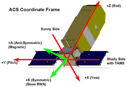
Figure 3‑1: ACS coordinate frames. Red: original, Green: revised for magnetic control system.
The basic operations concept for the ACS was to hold the satellite inertially fixed at the last commanded attitude, and to re-orient the satellite when a new attitude was commanded. Ordinarily, new attitudes would be commanded from observation scripts executing in the IDS. Slews could also be commanded from the ground, but this option was not used for science operations. The solar arrays were moved by the ACS during slews so as to be pointed at the Sun when the new attitude was reached.
The nominal configuration of the reaction wheels was to operate the skew wheel at a fixed speed, and to bias the other wheels in the opposite direction so as to maintain the total angular momentum stored in the reaction wheels near zero. This bias kept the wheel speeds away from zero, as bearing life and pointing performance were both expected to be adversely affected at very low wheel speeds. The magnetic torquer bars were operated continuously to remove excess momentum from the wheels.
Target acquisitions were scheduled after every slew and after every occulation of the target by the Earth. All observation sequencing and target acquisition logic was handled by scripts executing in the IDS. Processing of FES image data to locate stars and attitude determination from the positions of stars were performed by the IDS guidance task software. This division of functions between the ACS, IDS, and FES provided the performance necessary to meet the mission requirements and resulted in simple interfaces that facilitated rapid development and integration of the subsystems prior to launch.
The target acquisition process is described in Section 6.5, and further information on the ACS is provided in Sections 6.5.2 and 7.
Next: In-Flight Instrument Performance Previous: Instrument Design Table of Contents: Table of Contents