Design and predicted performance of the Far Ultraviolet Spectroscopic Explorer (FUSE)
David J. Sahnow, Scott D. Friedman, William R. Oegerle, H. Warren Moos
Center for Astrophysical Sciences, Department of Physics and Astronomy
The Johns Hopkins University, Baltimore, MD 21218
James C. Green
Center for Astrophysics and Space Astronomy
University of Colorado, Boulder, CO 80304
Oswald H. W. Seigmund
Space Sciences Laboratory
University of California, Berkeley, CA 94720
ABSTRACT
The Far Ultraviolet Spectroscopic Explorer (FUSE) satellite will obtain high spectral resolving power (/ = 30,000) measurements of astrophysical objects in the 905-1195 Å wavelength region from low-earth orbit. The instrument's high effective area (30 - 100 cm2) and low detector background will permit observations of solar system, galactic, and extragalactic targets that have been too faint for previous instruments at this high resolution.
The instrument design achieves both high resolution and high throughput by using four nearly identical optical channels. The optics consist of four normal incidence mirrors, four high density holographically-ruled diffraction gratings, and a pair of large format double delay line detectors. These components are supported by a graphite-composite structure. A commercially-procured spacecraft provides pointing stability of 0.5 arcseconds (1), by using data from a Fine Error Sensor included in the instrument.
In early 1995 the FUSE mission was restructured to be a lower-cost, PI-class mission. The construction phase began in December, 1995, and launch is scheduled for late 1998.
We present a description of the FUSE instrument, including details of the optical and mechanical design, along with an estimate of its on-orbit performance.
astrophysics, FUSE, spectroscopy, ultraviolet
1. INTRODUCTION
The spectral region between 900 and 1200 Å contains many of the most important atomic transitions for studying astrophysical processes. Since the Copernicus mission, launched in 1972, there have been no long duration missions to obtain spectra in this region. Shorter missions, such as HUT, IMAPS, and ORFEUS have shown the promise of the far ultraviolet. but they have not had the combination of effective area, resolution and wavelength coverage necessary to fully explore this region.
FUSE, the Far Ultraviolet Spectroscopic Explorer, was originally recommended by the Astronomy Survey Committee of the National Academy of Sciences in 1982(1) to address fundamental astrophysical questions in cosmology, galactic evolution, stellar processes, and planetary atmospheres. In 1986, FUSE was proposed as an Explorer mission, and in 1989 funding was awarded for design work.
Since that time, the FUSE program has undergone a number of major redesigns. As initially conceived, it contained a grazing incidence telescope and mechanically-ruled aspheric grating, and was meant to be attached to the Explorer Platform after reaching orbit via the space shuttle. Since then, the launch vehicle has been changed to a Delta II, and cost constraints forced a redesign to the current normal incidence design.
The FUSE program is a collaboration between the following organizations:
| Johns Hopkins University - Homewood | Science Oversight, Project Management, Systems Engineering, Mirror Assemblies, Integration & Test, Ground Operations |
| Johns Hopkins University -Applied Physics Laboratory | Instrument & Satellite I&T Facilities, Oversight of Spacecraft Development; Instrument Data System |
| University of Colorado | Optical Design, Spectrograph, Focal Plane Assemblies |
| University of California, Berkeley | FUV Detectors |
| Canadian Space Agency | FES |
| Orbital Sciences Corporation | Spacecraft |
| Swales and Associates, Inc. | Instrument Structure, Baffles, Thermal Design |
| CNES (France) | Diffraction Gratings |
2. SCIENTIFIC CAPABILITIES
The far ultraviolet wavelength region is particularly important to the study of physical processes in the universe because a large number of transitions of many important atomic and molecular species lie in this band. These include the resonance lines of atomic hydrogen and deuterium, molecular hydrogen, Ovi, Svi, Ciii, and many others. These transitions, seen in both absorption and emission, sample a wide range of temperatures, from 100 K to 106 K.
The FUSE top level requirements describe several major areas to which FUSE is expected to make unique contributions. Chief among these is measuring the abundance of deuterium, the heavy isotope of hydrogen. A variety of astrophysical observations indicates that luminous baryonic matter may comprise only a small fraction of the total mass in the universe. The remainder is thought to be composed of non-baryonic matter which has escaped direct detection. According to the standard model of the Big Bang, deuterium may be used as a direct measure of the baryon density, and therefore provides an alternate way to measure this critical cosmological parameter. Deuterium is easily destroyed in stellar and other processes, but is not thought to be created in any significant quantity due to its low binding energy. Thus, measuring the deuterium abundance in a variety of unprocessed, pristine environments is required in order to understand its primeval distribution. This is done by observing clouds of material seen in absorption against a bright background object, such as a quasar. The Copernicus satellite measured the deuterium/hydrogen (D/H) ratio toward approximately a dozen hot stars,(2) all within about 1000 parsecs of the sun, and more recently the Hubble Space Telescope has been used to measure it towards several other nearby stars.(3) This material is thought to have been heavily contaminated by stellar processing in our Galaxy, however, so it gives less certain information about the cosmological D/H ratio.
FUSE will be able to use more distant and fainter galactic and extragalactic sources to measure D/H in a variety of environments: the local interstellar medium, the halo of our Galaxy, and possibly the haloes of other galaxies. Several dozen lines of sight are available, which increases the probability that a number can be found which are simple enough to avoid confusion caused by multiple clouds. And since FUSE can observe all the lines in the Lyman series of hydrogen except Lyman-, it is capable of measuring the D/H ratio in clouds having a wide range of column densities.
Another important problem is the location and velocity structure of hot gas in the halo of the Galaxy. The lithium-like ion Ovi can be seen in absorption against extragalactic sources, and provides the means for making detailed measurements of the temperatures, densities, and velocities of this gas. This ion and several others in the FUSE bandpass are important for the study of supernovae and supernova remnants. Supernovae are an important source of heavy elements in the interstellar medium, and must be understood before a dynamical model of galactic evolution can be established. A timely event will occur near the end of this decade, when the ejecta from SN 1987A will interact with the previously existing circumstellar shell of material around the progenitor star, which should be observable with FUSE.
These science goals have dictated the design performance of the satellite. For example, the absorption spectrum along a typical line of sight in the interstellar medium will have many different velocity components. In order to separate these components and measure their physical properties, high spectral resolution is required. Velocities of order 10 km/sec can be distinguished with an instrument having a resolution of 30,000. To observe extragalactic targets in reasonable integration times (200,000 seconds or less) requires an effective area of about 50 cm2.
3. THE FUSE SATELLITE
The design of the FUSE satellite was driven by constraints of size, manufacturability, and cost. The instrument and spacecraft, which together make up the FUSE satellite, have been designed to have a very simple interface, in order to allow parallel development of the two sections, and to ensure a simpler integration flow.
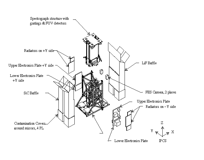
Figure 1. An expanded view of the intrument showing the major components. The spacecraft sits below the instrument.
3.1. Instrument
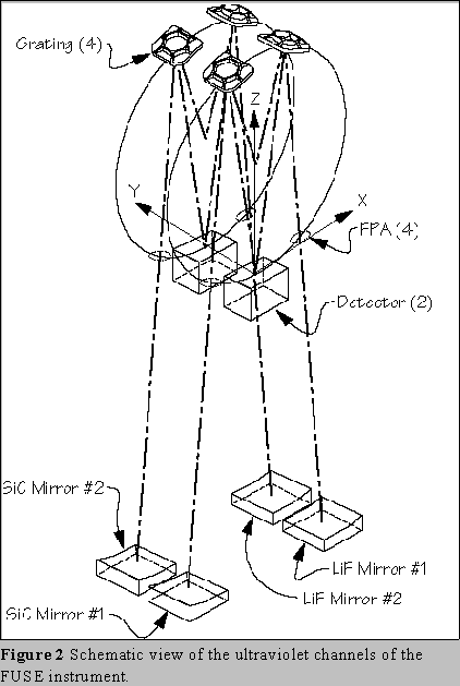 An
expanded view of the instrument is shown in Figure 1, and a schematic
view of the ultraviolet channels is shown in Figure 2. The design
includes four coaligned telescope mirrors; four Focal Plane Assemblies
(FPAs), each of which contains four apertures; four spherical,
aberration-corrected holographically-recorded diffraction gratings; and
two microchannel plate detectors with delay line anodes. The details of
the optical design of the spectrograph has been described elsewhere.(4) A visible light Fine Error Sensor (FES)
provides guide star position information which is used by the ACS in
order to allow subarcsecond pointing of the entire spacecraft. A
composite structure maintains the positions of the optical elements to
the several micron level during an exposure while the temperature is
controlled to 1 C. Some important instrument parameters are given in
Table 1.
An
expanded view of the instrument is shown in Figure 1, and a schematic
view of the ultraviolet channels is shown in Figure 2. The design
includes four coaligned telescope mirrors; four Focal Plane Assemblies
(FPAs), each of which contains four apertures; four spherical,
aberration-corrected holographically-recorded diffraction gratings; and
two microchannel plate detectors with delay line anodes. The details of
the optical design of the spectrograph has been described elsewhere.(4) A visible light Fine Error Sensor (FES)
provides guide star position information which is used by the ACS in
order to allow subarcsecond pointing of the entire spacecraft. A
composite structure maintains the positions of the optical elements to
the several micron level during an exposure while the temperature is
controlled to 1 C. Some important instrument parameters are given in
Table 1.
The four ultraviolet optical channels are divided into two pairs based on their wavelength coverage and coatings. The short wavelength channels, known as the silicon carbide (SiC) channels, cover from the low wavelength cutoff at 905 Å to approximately 1100 Å. Both the mirrors and gratings in these two channels are coated with SiC, which has a relatively constant reflectivity of 30%. The long wavelength channels extend from just below 1000 Å to 1195 Å. They are coated with lithium fluoride (LiF) over vapor deposited aluminum, and are known as the LiF channels. LiF has higher reflectivity than SiC above 1030 Å, but drops sharply shortward of this wavelength. Thus between them, the required 910 - 1180 Å range is covered.
This robust design was chosen to maximize the telescope collecting area and keep the gratings to a reasonable size while fitting within the limited constraints of the launch vehicle. Nearly the entire wavelength region is covered by more than one channel, and the important 1000 - 1100 Å region is covered by all four.
Each of the four mirror assemblies (telescopes) contains a nearly identical off-axis parabolic mirror with a focal length of 2245 mm. Each mirror is mounted on three actuators which allow movement in tip, tilt, and focus in order to maintain its coalignment and to ensure the telescope mirrors are properly focused to the gratings. Each actuator has a range of 2 mm, which allows for tilts of up to 20 arcminutes. The mounted mirrors are required to produce a spot containing 90% encircled energy within 1.5 arcseconds, in order to ensure maximum throughput when using the narrowest spectrograph slit. The mirror assemblies are described in more detail by Kennedy et al.(5)
The primary function of the telescope baffles is to reduce the scattered light from the earth so that faint targets can be used for guiding by the FES. The design of the baffles, and their expected stray light performance is described elsewhere.(6)
The light from each mirror passes through a slit in a FPA, which contains four apertures. These include a narrow (1.25
20 arcsec), high resolution slit, which guarantees the highest spectral resolution at the cost of some effective area; a wider (4
20 arcsec) high throughput slit which passes essentially all the light,
but provides lower resolution; a large square (30 30 arcsec) slit; and
a pinhole (0.5-0.7 arcsec diameter) for bright objects which would
otherwise overwhelm the detector. The FPAs can move in the focus
direction and along the Rowland circle in flight. This capability allows
adjustment for ground to orbit 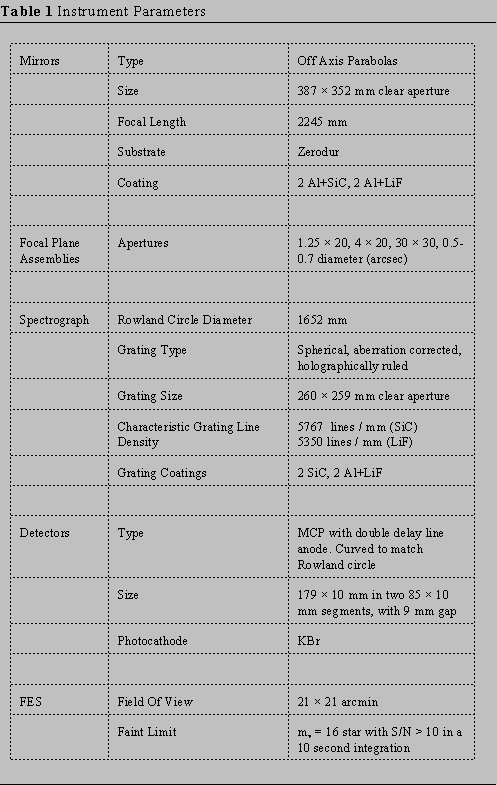 misalignments, on orbit focusing, and allows
high signal-to-noise detector flat field determination using an
iterative restoration technique.(7)
misalignments, on orbit focusing, and allows
high signal-to-noise detector flat field determination using an
iterative restoration technique.(7)
After passing through the slits, light reaches the spectrograph cavity, where it is dispersed by the diffraction gratings. Each channel has a 260 × 259 mm (clear aperture) grating with either a SiC or Al+LiF coating. The spectrograph is of Rowland circle design, with a diameter of 1652 mm. In order to correct for the aberrations, a holographically recorded grating with curved grooves(8) is used. Even with this correction, the image of a point source has a vertical extent of up to 0.9 mm, and the light from a monochromatic source creates a curved image on the detector. The gratings are supported by mounts which are designed to allow rotational adjustment about two axes during spectrograph alignment on the ground.(9)
Light from two channels (one SiC and one LiF) are dispersed onto separate areas on each of two detectors. The detectors are photon counting microchannel plate detectors with double delay line anodes, and they have an active area of 179 × 10 mm, divided into two 85 × 10 mm segments with a 9 mm gap between them. The front surface of the MCPs is curved to match the Rowland circle. Detector data can be collected in two modes: photon list, or spectral image mode. In photon list mode, the (x,y) position of each photon (along with pulse height) is recorded in memory for later transmission to the ground. In spectral image mode, the instrument flight computer accumulates a two dimensional histogram of the data, and only this image is sent to the ground. Photon list mode will be used for low count rate objects (< 1600 counts/second), which are expected to account for roughly 90% of the FUSE target time. Spectral image mode will be used at higher count rates, where on-board memory would otherwise be exhausted. A single segment prototype detector with flat microchannel plates has already been constructed.(10)
Pointing stability of the satellite is aided by a Fine Error Sensor (FES), which images a 21 arcminute square field around the slits in visible light. Centroids of up to six guide stars will be used to maintain the spacecraft pointing stability to 0.5 arcseconds, 1. Two FES are included in the design (one using each of the LiF coated mirrors, which have high visible reflectivity), but only one will be operated at a time. In order to improve the scattered light performance of the FES, the LiF channels will always be kept in the shade. The principal requirement on the FES is to provide centroids of stars as faint as mv=13.5 with an accuracy of 0.2 arcseconds, which will allow it to find at least one guide star in 85% of the fields at the North Galactic Pole.
The Instrument Data System (IDS) is a computer which is essential to operations of the instrument. The IDS processes the data from the FES and sends quaternions to the spacecraft attitude control system every second. The IDS also receives and stores photon event data from the FUV detectors. Finally, it stores and monitors housekeeping telemetry from the instrument subsystems.
Other important subsystems include the graphite/cyanate ester structure which is strong, thermally stable, and lightweight; a thermal control system which is designed to keep the temperature of the instrument to 0.5° C during an orbit in order to maintain the high throughput and resolution; and two stimulation lamps (one for each detector) which will be used for aliveness tests on orbit.
3.2. Spacecraft
After much of the design work had been completed on the instrument, a detailed spacecraft performance specification was prepared. The spacecraft designed to meet these specifications, which is being built by the Orbital Sciences Corporation (OSC), uses heritage from Explorer Platform, XTE and TRMM.
3.3. Integration and Test
Spectrograph integration and test will occur at the University of Colorado beginning in early 1997. At the same time, integration of the telescope mirrors, electronics cavity, and other components on the lower instrument structure will occur at JHU-APL. The fully aligned spectrograph will be shipped to APL, where it will be joined with the lower instrument. The spacecraft will be delivered to APL by OSC, where it will be integrated with the instrument, and a final instrument characterization will be performed.
4. MISSION OPERATIONS
Science and mission operations will be conducted from a Satellite Control Center (SCC) at the Homewood Campus of the Johns Hopkins University. An important characteristic of the FUSE ground system is the co-location of science and mission operations in a single facility. Previous NASA missions, such as IUE, HST and XTE, have maintained separate Science Operations Centers (SOCs) and Mission Operations Centers (MOCs). The primary objective of our approach in combining these control centers is to decrease development and operations costs. A side benefit is improved communication between the science planners and the spacecraft operators.
All ground system functions will originate at the SCC. These functions include planning and scheduling of observations, generation of command loads, communication with the satellite through autonomous ground stations, receipt and processing of science and engineering data, monitoring of the health and safety of the satellite and instrument, computation of FUSE's orbital elements, off-line analyses of science and engineering data, and maintenance of flight software.
4.1. Operations Concept
Science observations will be pre-planned weeks or months in advance, and will take place during the unocculted viewing intervals in low-Earth orbit. The total available exposure time is expected to be about 30,000 seconds per day (an average of 2000 seconds per orbit). This equates to an operational efficiency of about 33%.
FUSE will employ a network of autonomous ground stations for communications. The primary ground station will be hosted by the French Space Agency (CNES) and will be located in Kourou, French Guiana. Satellite telemetry will be downlinked at >1 Mbps to the Kourou station during the 8 orbits per day that this station is visible. When the primary station is not visible, data will be downlinked to the secondary ground station in Hawaii. A backup station in Puerto Rico will also be available for emergency use.
A high degree of autonomy will be built into the instrument to allow unaided target and guide star acquisitions, instrument alignment, and health and safety checks of the instrument by flight software. Observations will have the ability to proceed with no intervention from the ground, and, in the event of an anomaly, the satellite will revert to a known, safe state to await corrective actions from the ground.
The health and safety of the instrument and spacecraft will be checked at the SCC from a combination of real-time data, and downlinked stored telemetry. Command uplink at 2 kbps is needed infrequently (once or twice per day) for the upload of stored command sets. After the operations of the satellite have reached a 'routine' level, much of the checking of satellite telemetry will be performed autonomously by software. Anomalies will be logged for later review, and, in the event of detected emergencies, operators will be notified via beepers.
To the maximum extent possible, commercial hardware and software will be employed throughout the ground system to reduce development costs. This is made possible by the generally low data rates and relatively simple operations of the FUSE instrument, coupled with the availability of numerous low-cost commercially available products suitable for ground systems.
Science and engineering data will be archived at JHU in the short term, and at a remote location for the long term. Science data will be publicly available to the community via the internet six months after the data is obtained.
5. PREDICTED PERFORMANCE
As described above, the two main goals for FUSE are high resolution and high effective area. The highest resolution can be obtained by using the narrowest slit, which results in a loss of throughput. In addition, the most aberrated light may be discarded on the detector. The highest throughput is obtained with a larger slit, which may result in some degradation of the design resolution, depending on the telescope point spread function and the instrument pointing stability.
Since high resolution is required for the scientific problems that FUSE will address, the goal is to obtain spectra with a resolution of 30,000 over most of the 905 - 1195 Å wavelength band (and a minimum of 24,000) when using the high resolution slit. The current estimate for spectral resolution is shown in Figure 3. It meets this goal in at least one channel above 950 Å. The figure includes the effects of initial (long term) misalignments, and orbital (short term) variations due to distortions during an observation.
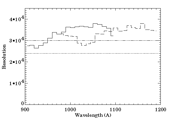
Figure 3. Predicted resolution of FUSE. The SiC (solid) and LiF (dashed) channels are shown separately. The resolution goal of 30,000 over 80% of the band, with a minimum of 24,000 is achieved.
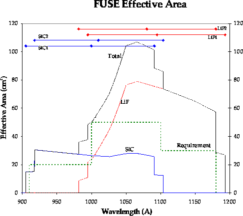
Figure 4. Predicted beginning of life effective area. The complicated shape is due to the differing number of channels contributing at each wavelength, the detector gaps, and the increasing reflectivity of LiF above 1025 Å.
Observations of faint objects will require high effective area in addition to high resolution. The current prediction of effective area at the beginning of life (assuming no throughput loss at the slit) is shown in Figure 4 (A degradation of approximately 20% per year after this has also been budgeted). The complicated shape is due to a combination of the varying number of channels contributing at different wavelengths, detector gaps, and the effects of the LiF cutoff at 1025 Å. This effective area should allow observations of objects as faint as 5 10-14 erg cm-2 s-1 Å-1 with a S/N of 20 in 105 seconds.
Since the instrument is optimized for observing faint objects, it will be necessary to limit the flux for the brightest targets, such as those observed by Copernicus, in order to avoid overwhelming the detector and data system. Brighter objects (fluxes greater than 3 10-10 erg cm-2 s-1 Å-1) will require use of the pinhole aperture, or placing the target off the edge of one of the larger slits, allowing only light from the wings of the point spread function to enter the spectrograph.
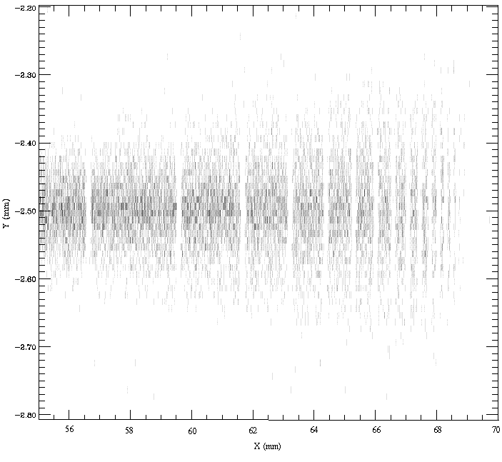
Figure 5. Results of a SiC channel simulation showing the spectrum collected in 2000 seconds from an object with a continuum flux of 3 10-12 erg cm-2 s-1 Å-1. The Lyman series of Hydrogen is visible out to the Lyman limit at 912 Å on the right hand side of the figure (wavelength increases to the left), due to hydrogen column desnity of 1019 cm-3. Note that the x and y scales are different.
Due to the astigmatic nature of the spectra on the detector, the
pipeline processing of the data will require turning the complicated,
two dimensional image on the detector into one dimensional, fluxed
spectra. Preliminary models using simple straightening algorithms have
been developed, but more sophisticated algorithms will be developed over
the next year in preparation for integration and test. Figure 5 shows a
portion of a simulated SiC channel spectrum on the detector for a 2000
second exposure of an object with a continuum flux of 310-12
erg cm-2 s-1 Å-1. The Lyman
series of hydrogen is visible out to the Lyman limit at 912 Å on
the right side of the figure (wavelength increases to the left), due to
a hydrogen column density of 1019 cm-3.
6. CURRENT STATUS
All subsystems are now under construction. Two SiC flight gratings and one flight spare have been delivered to the University of Colorado, and coated at Goddard Space Flight Center (GSFC). They await testing later this summer. The instrument structure is scheduled to be delivered to the University of Colorado later this year, and spectrograph integration begins there in early 1997. After integration, the spectrograph will be shipped to JHU-APL, where overall instrument integration will begin in December 1997, and integration with the spacecraft will start in March 1998. Launch is set for November 1998.
Additional information about the FUSE mission and the science program may be found on the FUSE homepage on the World Wide Web, at http://fuse.pha.jhu.edu
7. ACKNOWLEDGEMENTS
This work was supported by NASA contract NAS5-32985.
8. REFERENCES
1. G. B. Field et al., Astronomy and Astrophysics for the 1980's, National Academy Press, 1982.
2. D. G. York and J. B. Rogerson, Jr., "The abundance of deuterium relative to hydrogen in interstellar space," Ap. J. 203, 378-385, 1976.
3. J. L. Linsky et al., "Deuterium in the local interstellar medium: properties for the Procyon and Capella lines of sight," Ap. J. 451, 335-351, 1995.
4. J. C. Green, E. Wilkinson and S. D. Friedman, "The design of the Far Ultraviolet Spectroscopic Explorer spectrograph," Proc. SPIE 2283, 12-19, 1994.
5. M. J. Kennedy, S. D. Friedman, R. H. Barkhouser, J. Hampton and P. Nikulla, "Design of the Far Ultraviolet Spectroscopic Explorer mirror assemblies," Proc. SPIE 2807, 1996.
6. K. I. Mehalick and C. L. Morbey, "Stray light analysis of the Fine Error Sensor of the FUSE instrument," Proc. SPIE 2864, 1996.
7. D. J. Sahnow, C. W. Bowers, O. H. W. Siegmund, J. Stock and M. A. Gummin, "FUSE microchannel plate detectors: models and data for resolution at the pore limit," Proc. SPIE 1945, 390-397, 1993.
8. R. Grange, "Aberration-reduced holographic spherical gratings for Rowland circle spectrographs," Appl. Opt. 31, 3744-3749, 1992.
9. A. F. Shipley, J. C. Green and J. P. Andrews, "The design and mounting of the gratings for the Far Ultraviolet Spectroscopic Explorer,' Proc. SPIE 2542, 185-196, 1995.
10. O. H. W. Siegmund, et al., "Delay line microchannel plate detectors for the Far Ultraviolet Spectroscopic Explorer Satellite," Proc. SPIE 2209, 388-399, 1994.